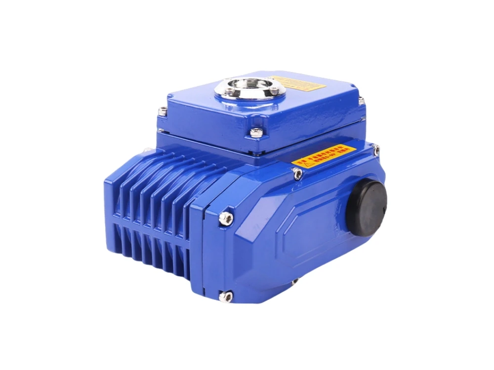
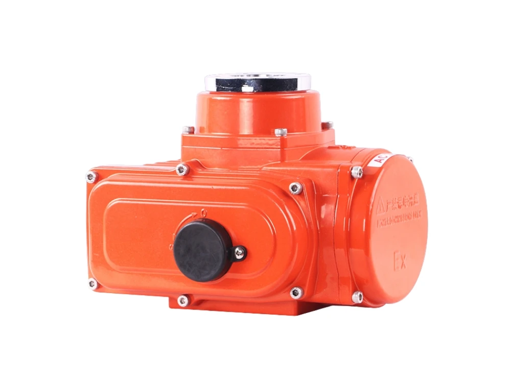
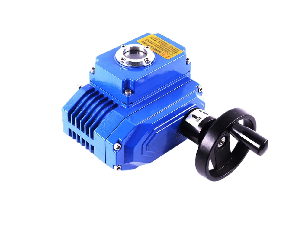
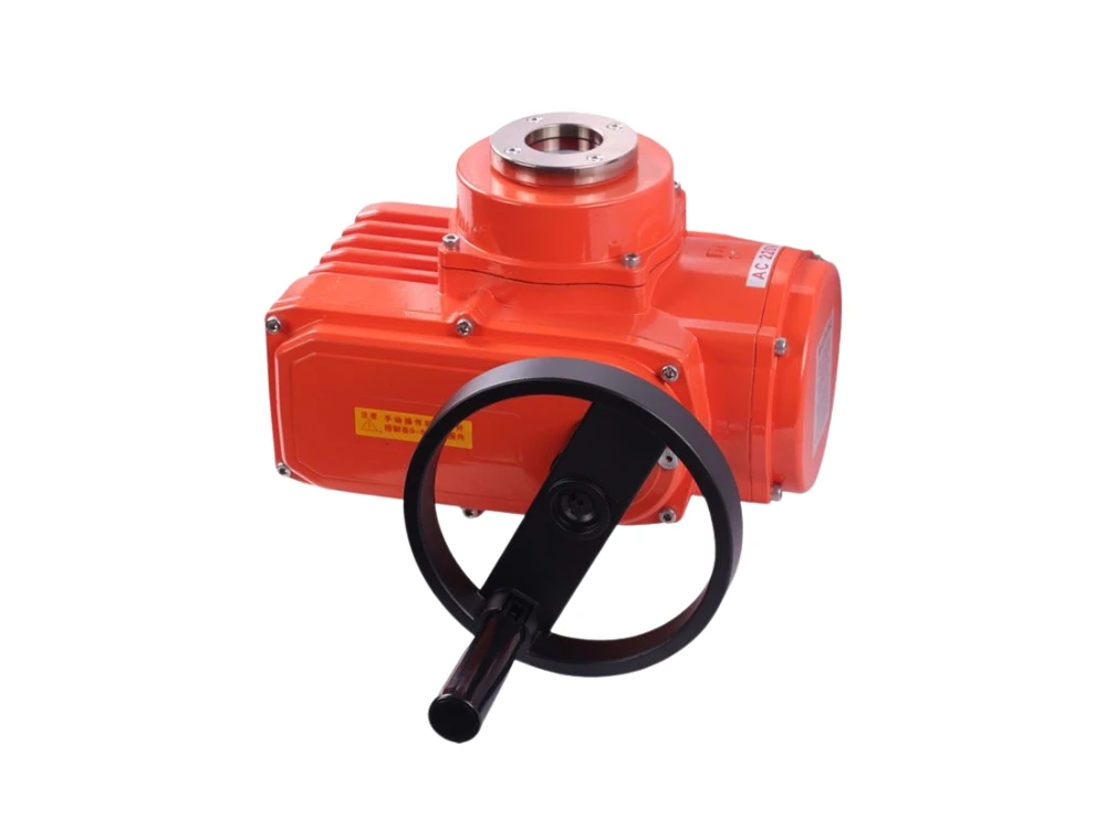
How To Debug The Electric Actuators?
Debugging steps:
-
Check that the appearance of the actuator is complete and the signals match;
-
Complete the wiring of the actuator and check whether the wiring is correct.
-
Wiring of the actuator:
- Power cord, 220V or 380V. Pneumatic valve positioners generally do not require a dedicated power cord;
- Analog signal: command signal 4-20mA DC, from DCS or PLC to the actuator, feedback model 4-20mA DC, from the actuator to DCS or PLC, etc.;
- Switch signal (optional): fully open, fully closed travel switch signal, fault signal, etc.
-
Before ventilating, manually adjust the actuator to the middle position, then set the operation mode to “local operation”, turn on the power, and first move the actuator to see if the running direction of the actuator is consistent with the direction of the valve action. If it is the opposite, then It is necessary to commutate the power line or change the forward and reverse action mode of the actuator.
-
Adjust the limit: Use the actuator to move the valve to the “fully closed” position, set the multimeter to the buzzer position, and measure whether the “open point” of the close limit changes to the “closed point”; if there is no change, then It is necessary to adjust the closing limit until it is adjusted properly; then move the valve to the “fully open” position and see if the “open limit” signal comes, otherwise the limit needs to be adjusted.


