How to Select Valve Accessories Filter Regulator?
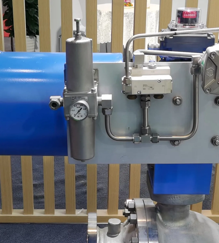
The correct selection of valve accessories is significant for the reliable and stable operation of pneumatic valves. The control circuit of the valve consists of each accessory, improper selection or failure of the valve accessories will lead to abnormal action or refusal of the valve action, bringing great safety hazards to the process.
The compressed air output from the compressor contains a lot of moisture, oil dust, and other pollutants. It is the “killer” of our pneumatic components.
Degraded oil forms tar-like substances, resulting in rubber and plastic material deterioration and aging.
Moisture has a greater impact on pneumatic components: pipeline metal rust, and water ice, so the lubricating oil deterioration and flushes off the grease.
Rust debris and dust will make the relative moving parts wear, and accelerate the seal damage, resulting in air leakage.
Pressure-reducing valve is the higher inlet pressure, adjusted and reduced to meet the requirements of the use of the outlet pressure (regulator). And to ensure the stability of the outlet pressure after adjustment (pressure stabilization) of the device.
Each pneumatic valve control circuit is equipped with a filtering pressure-reducing valve at the front end, which plays a role in compressed air filtration and pressure stabilization.
The use of environmental selection
1.1 The place of direct sunlight, should choose the all-metal material products. If there are plastic or resin materials, to avoid deterioration by ultraviolet radiation or temperature rise, should be shielded from sunlight.
1.2 For places with a lot of rain or dust, products with rainproof and dustproof functions should be used.
1.3 Surrounded by heat sources, ventilation, and poor places (to prevent softening damage caused by radiant heat, should be shielded from heat sources).
1.4 Offshore environment, should be considered anti-salt spray corrosion treatment or selection of stainless steel.
1.5 In the environment containing or attached to organic solvents and chemicals, the physical properties will deteriorate. In the case of the above factors, or the case of suspicion, metal cups should be used for safety.
1.6 When used at low temperatures, the freezing of water may cause damage to seals and malfunction, so take measures to prevent freezing.
1.7 Frequent pressure inflation and deflation in the standard cup of the filtering pressure-reducing valve may damage the cup. In the above case, a metal cup is recommended.
1.8 If leakage to the surrounding environment is not permitted, or if a fluid other than air is used, select a product with a collectible exhaust.
1.9 Confirm the “IN” and “OUT” markings on the compressed air inlet and outlet, or the direction of the arrows, and make the connections. Reversing the connection may cause malfunction.
1.10 The water cup of the air filtration and pressure-reducing valve should be installed vertically facing downward to prevent poor drainage and secondary contamination of the air supply.
1.11 Space for maintenance and operation should be left above, below, and in front of each product.
Technical parameters selection
2.1 Use of fluids. When using fluids other than compressed air, please contact the manufacturer for confirmation.
2.2 Operating temperature. The operating fluid temperature and ambient temperature are fixed. If the temperature is exceeded, damage, malfunction, or malfunction may result. -Usually, the ambient temperature range of the filter pressure-reducing valve is -5~60℃ for the normal temperature type; -30~60℃ for the low-temperature type; -40~80℃ for the special temperature type.
2.3 Use pressure. Select the use pressure of the filtering pressure-reducing valve according to the size of the gas source pressure. Damage, malfunction, and poor operation will be caused when it is used beyond the range. The pressure resistance of normal filtering pressure-reducing valves is 1.5 MPa, and the maximum operating pressure is 1.0 MPa. Special pressure ranges can be selected by contacting the manufacturer.
2.4 Setting pressure. According to the permissible operating pressure of the downstream equipment, select the appropriate set pressure range of the filtering pressure-reducing valve. The set pressure range of normal filtering pressure-reducing valves is 0.05 ~ 0.85 MPa; a special pressure range can be selected by contacting the manufacturer.
2.5 Filtration accuracy. The standard filtration accuracy of the filtering pressure-reducing valve for instrumentation is 5 μm.
2.6 Connection diameter and flow rate characteristics. Calculate the required flow rate of the circuit according to the volume and speed of the pneumatic actuator. According to the required flow value, select the corresponding filtering pressure-reducing valve and piping caliber.
2.7 Drainage method. The drainage method of the filtering pressure-reducing valve is divided into automatic drainage type and manual drainage type. Usually, manual drainage is selected when the valve is individually assembled and used, and automatic drainage is selected when the valve is centrally assembled in the control cabinet. When used in a low-temperature environment, the automatic drainage type cannot be selected.
Principle of operation
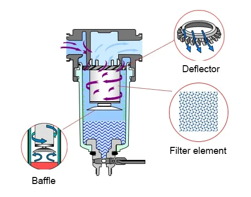
The working principle of the filter
Explanation of the working principle of the filter:
The compressed air flowing in from the inlet is strongly rotated through the notch in the tangential direction of the deflector plate, and the liquid oil water, and solid pollutants are centrifuged and thrown to the inner wall of the water cup and then flow to the bottom. The compressed air with liquid oil and water and large particles of contaminants are removed, and tiny particles are further removed through the filter element, which then flows out from the outlet. The gear plate prevents the liquid oil and water in the lower part from being swept back into the air stream. Condensate that accumulates in the water cup can be discharged from the drain port by pressing the manual button.
Filter element: The sintered metal filter element is resistant to high/low temperatures, rinsing, and stable filtration performance, and can be removed and cleaned when there is too much sludge, making it highly reusable. When the pressure difference between the inlet and outlet is more than 0.1MPa, or when the usage time is more than 2 years. Please replace the cartridge!
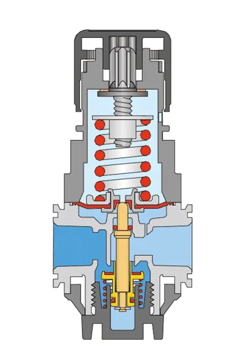
Working principle of the pressure-reducing valve
Explanation of the operating principle of the pressure-reducing valve:
Pull the handwheel outwards and turn it clockwise.
The regulating spring is compressed, pushing the diaphragm downward and opening the valve spool through the valve stem, then the inlet gas pressure is regulated by the valve spool to reduce the pressure, and the pressure is output.
Outlet pressure gas through the feedback path into the lower chamber of the diaphragm, on the diaphragm to produce an upward thrust.
Eventually, the pressure of the lower part of the diaphragm and the upper part of the spring force are the same (when the thrust force is balanced with the regulating spring force), and the outlet gets stable gas pressure.


