How To Troubleshoot Electric Actuators?
Overview of Electric Actuators
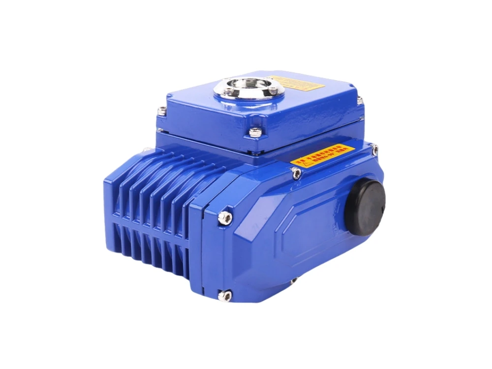
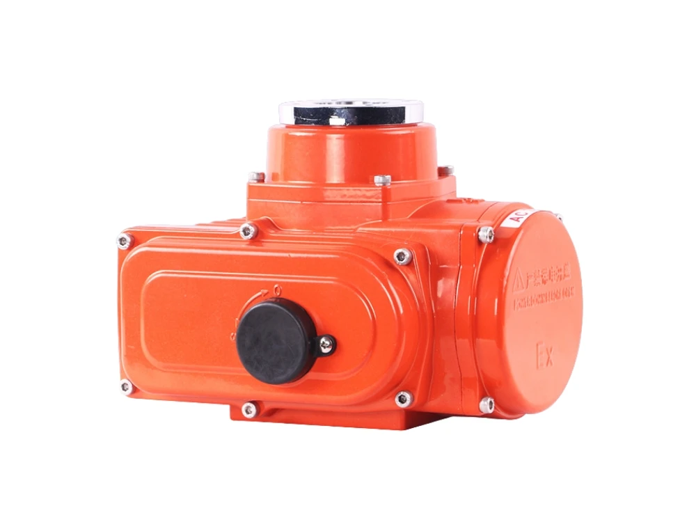
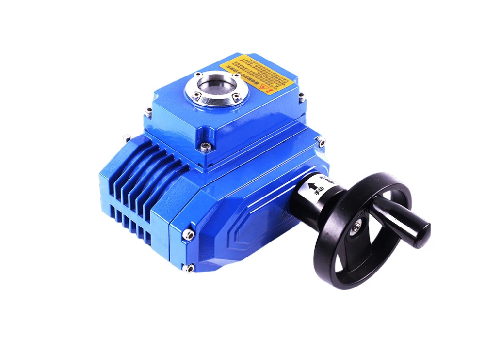
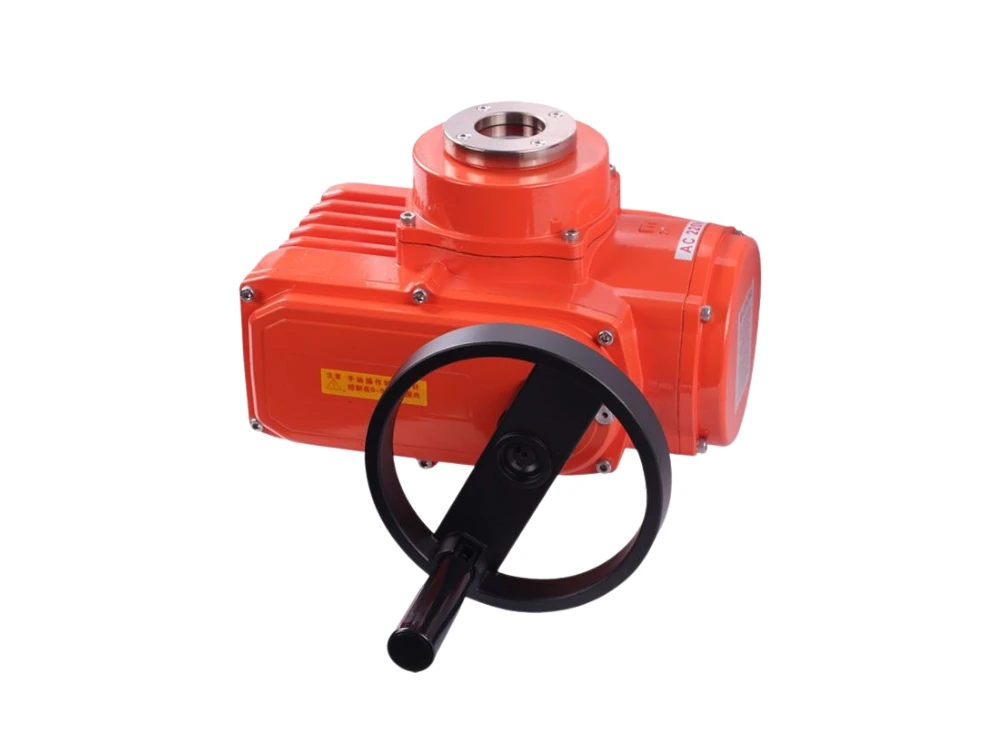
The actuator electric is mainly composed of a power board, a main board, a stroke detection device, a torque measuring device, an AC contactor or a frequency converter, a motor, and a reducer. The electric actuator uses a small motor to drive the first-stage reducer worm gear, which can output multi-rotation motion, angular stroke motion, and linear stroke motion to the valve. The motion output form of the electric actuator is determined by the characteristics of the controlled valve.
If the working torque required by the controlled valve is particularly large, such as greater than 2000 NM, a secondary reducer is usually added. The actuators electric directly drives the secondary reducer, and then the secondary reducer drives the valve movement; the protection of the electric actuator usually includes valve position protection, torque protection, motor overheat protection, motor stall protection, control unit fault protection, power supply fault protection, etc. The handling of the fault should be carried out in a targeted manner according to the alarm information of the electric actuator.
Loss of valve position of electrical actuator
Battery power loss
When using an incremental encoder to measure stroke, the actuator must have a battery as an auxiliary power source. When the AC power disappears, the change of the valve position of the electric actuator can still be detected by the incremental encoder, and the full open position and full closed position of the electric actuator will not change. If the AC power disappears and the battery power is exhausted, when the actual valve position of the electric actuator changes, the incremental encoder cannot detect the change of the valve position, resulting in the loss of the valve position. When the AC power is restored, the default valve position of some manufacturers’ products is 50%; some manufacturers using incremental encoders have made improvements in hardware and added capacitor circuits. When the AC power disappears, the valve position is saved by using capacitors to store electrical energy. However, the electric actuator cannot be manually operated when there is no battery power, otherwise the valve position will still be lost. Therefore, when the battery power is low, replace the battery in time.
Hardware damage
Electric actuator encoder disconnection, the encoder input voltage is too low, the travel transmission gear is damaged, the encoder circuit board is corroded, and mainboard travel detection and storage components are damaged, all of which can cause abnormal changes or loss of valve position. When handling, confirm that the encoder input voltage is normal, and replace the mainboard or the travel encoder to eliminate them one by one.
Torque failure of electrical actuator
Torque protection refuses to work.
To measure the output torque of an electric valve actuator, there are mainly mechanical protection switches, motor current voltage power measurement and calculation of torque, and sensor protection devices: Mechanical torque protection switches were used more frequently before 2000 and are a transitional product. Some low-end electric actuators are still using them. This type of torque protection switch can only provide switch quantity for torque protection, and cannot provide real-time data of process torque, and the measurement error is large; the torque is calculated by using the motor current voltage and the phase angle between the current and voltage, which requires a software program to implement; the sensor torque protection device combines the axial deformation of the first-level worm of the electric actuator with the pressure sensor, amplifies the voltage output by the pressure sensor through the circuit board, and then inputs the signal to the control main board to obtain the real-time torque value of the electric actuator.
Torque protection refusal to work is mainly manifested in the tripping of the actuator AC power supply, severe wear of the worm gear of the electric actuator, bending and deformation of the door rod, and even the breaking of the screws connecting the electric actuator and the valve. The torque protection value should be reset and verified with a torque calibration bench. When selecting valve torque, it is necessary to ensure that the actuator can reliably switch the valve, and the torque of the electric actuator must not exceed the maximum torque that the valve stem can withstand. There are certain difficulties in parameter setting because the maximum torque that each valve stem can withstand is often not easy to obtain. Electric actuator manufacturers often set torque parameters based on experience, first set a smaller torque protection value, and if the torque protection is activated, then increase the torque protection parameter setting appropriately until the valve can open and close normally in the cold state. If the torque protection is activated in the hot state, continue to increase the torque protection value appropriately to ensure that the valve can open and close normally in the hot state.
Torque protection misoperation
When the manual operation of the electric valve actuators is light, the over-torque protection action occurs. After eliminating the torque protection value setting too small, for intelligent electric actuators, observe the LCD screen torque value prompt or the indicator light showing over-torque information. By rotating in the opposite direction, the over-torque signal in the original direction should disappear. Otherwise, the mainboard or torque detection device should be replaced to eliminate them one by one.
For mechanical torque detection devices, turn the motor actuator in the opposite direction and check that the torque switch should be disconnected. Otherwise, the torque protection switch should be replaced. If the torque protection switch has been set to the maximum value and it is still over-torque, it should be considered whether the torque selection of the electric actuator is too small.
The specific reason why the electric actuator motor rotates but the actuator output shaft does not rotate
The electric actuator is engaged on the manual side. After the electric actuator motor rotates, the switching device fails to engage on the motor side, causing the motor to idle.
The worm gear driven by the electric actuator wears and slips, causing the motor to idle and the actuator output spindle to not rotate.
One of the three phases of the motor power line is not in reliable contact, causing the motor to rotate sometimes and not rotate sometimes.
For the electric actuator motor idling, after judging that the power supply is not faulty, the electric actuator primary worm gear box must be opened to check the wear of the worm gear. If the wear is serious, it can only be returned to the factory for repair or replaced with a new electric actuator; the switching device failure can generally be repaired on-site according to the working principle of the switching device of different electric actuators.
Causes of overheating of the electric actuator motor
Frequent operation of the electric actuator causes the motor to overheat and triggers protection action.
The thermal resistor-type temperature measuring element is disconnected or the terminal is in poor contact, which falsely generates an overheating signal.
The motor rotor bearing is damaged and cannot rotate, and the motor is blocked, causing the motor to overheat.
For motor bearing damage, the bearing should be replaced; when the temperature measuring element is damaged, the motor should be replaced, because the stator coil needs to be disassembled to replace the temperature measuring element alone, which is too expensive, and the cost is enough to buy a new motor with hundreds of watts of power.
Reasons why the electric actuator cannot be operated locally or remotely
The power board is faulty. The power board provides control power to the main board. If the power board fails, it may cause the remote and local operations to fail.
The main board may fail, which may cause the control instructions to fail to execute.
Power supply failure, the electric device detects that the power supply is missing or there is no power supply, and the electric actuator cannot operate.
This type of fault can only be eliminated by replacing the main board and power board one by one because the place of use generally does not have the conditions for testing the circuit board.
Reasons for the electric actuator to have no full open and full closed feedback
The terminal position relay is faulty and cannot be closed or opened reliably.
The relay is set incorrectly.
The main board is faulty.
When handling, first check the terminal position setting to ensure that the setting is correct; for relay failure, if the position relay is installed independently, replace the position relay; if the position relay is welded to the main board, replace the main board.


